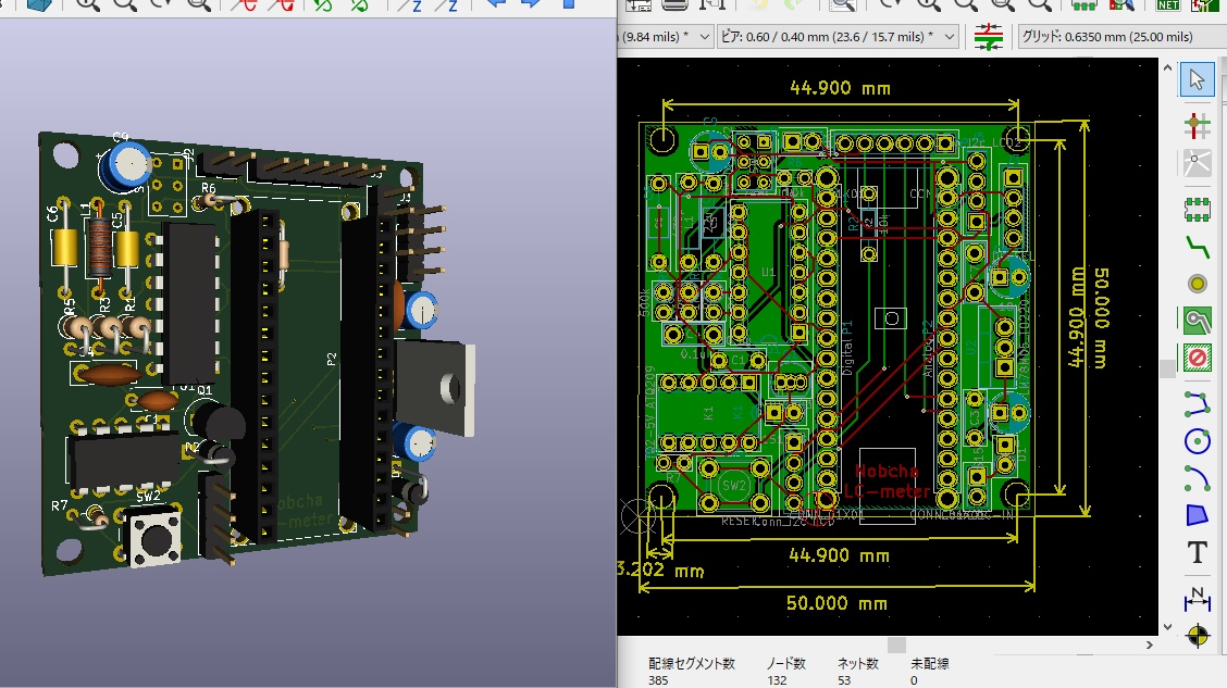
franclin発振回路を使い、Arduinoで制御するLCメーターを色々と触っています。

基板を作って実験を進めています。測定値がなかなか安定しないので原因をLTspiceから推定しました。fanclin発振回路はコルピッツ/ハートレーなどの発振回路と違い、浅いバイアスの増幅回路で動作しているので、発振安定に至る時間が長く、外乱に弱いようです。
LTspiceでみても、発振安定まで電源ONから数百mSかかるようです。

なので、Arduinoのスケッチを修正し、発振条件切替ごとに0.5秒程度のDelay()を入れました。スケッチV2.4はGITHUBに掲載しています。
電源ONからキャリブレーション、測定までの操作説明をYOUTUBEに掲載しました。
youtu.be
改良版がJasonKitsから販売されました。
I'm trying LC meter of Franklin oscillator by Arduino. I had made PCB and assembled it. I estimated the cause of measuring instability.
Franklin oscillator is based on A-type amplifier on sharrow biassing unlike the Colpitts or Hartley oscillator. By LTspice simulation, .tran result reported slowly winding up of oscillation.
Accordingly, I reedited the sketch of Arduino to take some timing between parameter switching chances.
If you would like to make the bare PCBs, please resister PCBGOGO URL:https://www.pcbgogo.jp/promo/nobcha23
. Then you can get the coupon that you shall pay only 1USD with shipping to make the 5 PCBs. There is the Gerber data for that.
github.com
I will introduce how to operate the LC meter on YOUTUBE.
If you are interested in this circuit, you can purchase the improved version as below.
www.tindie.com
Jason Kits is selling the similar kit which had been diverted from this project.
Inductance-Capacitance Meter AVR - AtMega 328Pwww.tindie.com