nobcha23の日記

PICマイコンやArduinoを使う電子回路遊びを紹介します

i2c SCANでデバッグ進展 i2c scanning sketch is useful

TA2003,Si5351a,Si4732などを組み合わせたエアバンド受信機の基板をデバッグしています。
始めに見つかったバグはRF基板からの電源入力供給すると異常電流が流れることでした。この原因はパネル部基板でRAWと+12V電源入力端子をつないでいたからでした。RF部基板からの+5VがPANEL部のLT1117を逆流し、Arduino pro miniに流れ込んでいたようです。ともかくRAWと+12V-VINのパターンをカットしたら治りました。
I’m going to debug the airband receiver PCB combining with TA2003, Si5351a, Si4732 and peripherals. The first found bug was to source irregal current from RF PCB to Panel PCB. This was caused by connection RAW with +12V in. The +5V supply of RF PCB may go reversely from LT1117 into RAW. I cut the connection trace and resolved.

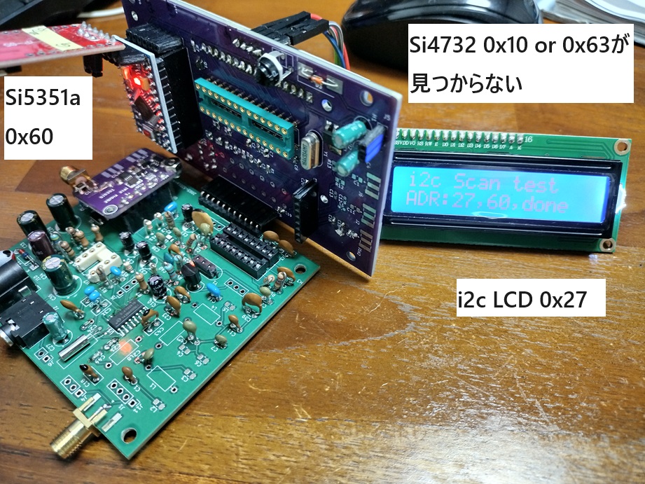
次にはSi4732が動かなくて原因を探っていました。
Arduinoは以前作成したpro mini/ATmega328P搭載の1602A表示PANEL部を使っています。
The next issues are no starting og Si4732. I'm using the Panel PCB with mini/ATmega328P and 1602A.
I took up i2c scanning sketch and Si5351a/i2cLCD worked well.

まずはi2cに応答してくれないことには始まらないので、手始めにi2cスキャンスケッチを作って探りました。
Si5351aやi2cLCDはちゃんと引っ掛かります。

i2cスキャン Si4732:0x11 or 0x63 ? 

で、原因は次の二つでした。
i2cスキャンに応答しないし、32.768kHz水晶が発振していないので焦りましたが、原因究明できました。
I found two issues for this.

1.アースべたパターン指定でSi4732のGND端子はべたパターンとつながっていたが、べたパターンは浮いていた。回路図エディタでGNDピン#15をGND接続した後、最後にべたパターンをGND指示したはずなので、なんだかおかしい。べたパターン指定後、念のためのVIAホール指定が不足していたのは不注意だった。I edited Si4732 #15 to connect to GND and after then I added the solid patern for this area. However KiCAD may discard this connection. I unfortunately missed to add the via holes for this solid patern.

2.RESET端子#9につながるArduinoポートがPINMODE指定なしでRESET端子が浮いてGNDレベルになっていた。3.3V/5V問題あるが、とりあえず5Vでプルアップ。
Reset node of #9 is open condition of GND when Arduino Pinmode not active.

Si4732:0x11見つかった

i2cスキャンスケッチのリンク
http://chitose6thplant.web.fc2.com/AB/R909/i2c_scnner_R909PANEL.txt

今PCBGOGOに新規ユーザー登録すると、基板代1ドル、送料無料のサービスが受けられます。
次のリンクからどうぞ。
www.pcbgogo.jp


PCBGOGOの入稿データチェックで助けられましたーー担当エンジニアさんに感謝

TA2003,Si5351a,Si4732などを組み合わせたエアバンド受信機の基板を設計しています。
先日はRF部を設計試作し、部品集め実装に手間取り、やっとPU2CLRのライブラリーが走ったところです。

Si4732を半田付け

Arduinoを搭載したPANEL部は以前作成したpro mini/ATmega328P搭載の1602A表示で実験しています。
アルミのケースを入れたいと思い、OLED表示&ATmega328P搭載のコンパクトサイズ基板を設計してみました。

そしてPCBGOGOに製作依頼しようと入稿したところ、受付のエンジニアから、コメントが返ってきました。
寸法線がパターン面データに入っていて、おかしなパターンになっていますよとのこと。
よく見ると、KiCADの操作ミスで参考用寸法線と寸法数字がA面データに入ってました。

PCBGOGOではMyPageを開くと、画面の上に担当営業さんのボタンが出てきてクリックしてメッセージやりとりするようになっています。
担当営業さんが付いて、日本語でやり取りできるので、ワタシのようなポカミスを防いでもらえました。感謝。

PCBGOGOのマイページ

すぐにデータを修正し、送りなおしました。その基板ですが、休日も入りなんと5日で到着です。これは国内と変わらない時間感覚です。
前回はDHLでしたが、今回は運搬費安いOCSなのですが、一日早く着いた。これも驚き。

到着荷物

PCBGOGOリンクwww.pcbgogo.jp


PCBGOGOのプリント基板が入稿から6日で完成到着

PCBGOGOに依頼したプリント基板ですが、19日にデータ入稿し、20日にチェックOK&行程投入、21日に完成、DHLに乗って、24日本日到着です。

仕上がりをルーペで見ましたが、スルーホールやパターン、スルーホール穴やはんだマスクの位置づれなども見当たりません。これで2ドルとは信じられないです。

到着基板

不足する実装部品を今月始めにAliに頼んであるんですが、そちらの方が届きません。Aliの最近の格安輸送ではメインランドから台湾郵政に一旦依頼し、その後台湾から発送するようで、トラッキングが効きません。チャイナポストなんかでは成田とかKIXについて通関後、佐川やヤマトに載せ替えられてからもトラッキングが効くんですが。

www.pcbgogo.jp


日本語対応中国メーカーPCBGOGOで1ドルプリント基板作成ーー実際は手数料あり、2ドルでしたが、とにかく安い

動くかどうか心配ある基板を作るのになるべくお金はかけたくありません。そこで最近大流行りの中国基板メーカーの割引サービスを試しました。

「ホームページ日本語対応」、「KiCADプラグインあり」、「日本語堪能なスタッフによるコンサルティングあり」、「初回注文は基板1ドル、送料無料」のPCBGOGOを試しました。
基板作りには色々お約束、ノウハウあり一筋縄でいきませんので、注文前コンサルティングサービスは転ばぬ先のつえでありがたいサービスですね。

さて、現在、TA2003のミキサー、Si5351aを使い周波数制御、Si4732で受信機動作させる航空無線受信機試作に取り組んでいます。

この間は第一ステップ、パネル部として、Arduino pro mini/ATmega428とSi5351aを作りました。そして、その回路にR909受信機の1602LCDスケッチを移植。更にCesarSoundさんのSSD1306表示のスケッチも移植しました。


今回の基板はRF部です。局発信号を引っ張りたくないのでRF部にもSi5351aを載せます。これはVFOで使うときはパネル部に、受信機ではRF部に載せるという構成です。ブロックダイアグラムは次のようになっています。

R909 SDR1 Block diagram

さて、次に今回のPCBGOGO基板への注文で気の付いた点を紹介したいと思います。

1.KiCADV7.0のプラグイン (KiCAD V7以降)
KiCADで基板パターン設計を終え、製造用のデータ準備に入ります。ガーバーデータファイル作成にPCBGOGOのプラグインが用意されています。これは便利ですよ。

KiCADプロジェクト開始メニューの一番下、プラグインをクリックして、出てくるPCBGOGOを選択します。

PCBGOGOプラグイン

2.製造データ作成とアップロード
プラグインが入っていると、パターン設計終わった時点で、プルダウンメニュー「ツール」の中、外部プラグインでPCBGOGOを選ぶと自動的にプロットして、ガーバーファイル類をzip化し、PCBGOGOの注文画面迄飛んで行って、ファイルをアップロードしてくれます。

ファイルアップロード

しかしながら、ここで残念なのは、行き先は英語画面で、日本語に切り替えマイページにする必要があるところです。
切り替えると、せっかくのアップロードは無効になりますが、心配ありません。マイページの「基板製造見積」画面からKiCADのワーキングディレクトリーに入っているzipをアップロードします。

アップロード

3.コンサルティングサービス
PCBGOGOでは会員ごとに日本語のできる担当が割り当てられるようです。マイページの上に出てくるポップをアクセスしてメールを出すと、就業時間中ならすぐに回答が来ます。今回の注文では面付けVカットはどうなのかを聞いてみました。面付とかルータカットとかいろいろなメニューは割引基板では対応できませんとのことでした。KiCADのパターン編集で自分で面付しVカットやマウスバイトなど入れなければ(自分でソーやNTカッタで切り離す)良いみたいです。
基板データを入稿すると進捗状況がチェック待ちになり、終わるとメールが来て、支払いに進みます。

4.支払い
PAYPALかクレジットカードです。基板代が1ドルになり、送料が差し引かれ、でもPAYPAL、クレカ手数料は必要です。料率は5%で切り上げなので、1ドルになりました。ということで2ドルで基板を作ってもらえることになりました。初回の送料無料はすごくありがたいです。

決済

と言うことで無事注文できました。来週早々にはRF基板が来るんだろうと期待し、実装部品を集めているところです。到着したらまた報告します。

PCBGOGOに会員登録し、初回送料無料で基板代1ドルを試してみてください。
www.pcbgogo.jp


Arduino C meter 2 option 充電時間計測のCメータ追加 (3/3)

いったん挫折し外付け抵抗2.2MΩでの充電時間計測Cメータを試しました。でもやっぱりもう一度内部プルアップ抵抗利用充電時間計測Cメータをやってみました。

「ATmega内のプルアップ抵抗による充電時間コンデンサー値測定法」です。充電時間(時定数)をATmega内のプルアップ抵抗使い測れるか試しました。 pinMode(DIGITAL_WRITE_PIN, INPUT_PULLUP);コマンドでPULLUPを指定した時に内部で接続されるであろう抵抗です。WEB情報だと大体10~30kΩあるとのことです。実験では手持ちのUNOで約43kΩありました。

測定アプローチですが、次です。
1. 標準C(充電時間とADCのサンプルレートを勘案し104Jを使う)を付け、測定値から内部抵抗値を計算。
2. 覚えておいた内部抵抗値から試験Cの充電時間を計測して、容量値を計算。


I had reported "C meter refered with stray capacitance of Arduino MPU nodes" ever. That can measure small value. This time I tryed the other way to measure charging time( time constant ) by using the internal resister of Arduino. We can use it as command of pinMode(DIGITAL_WRITE_PIN, INPUT_PULLUP);. Someone said the value is 10 - 30 k ohm. Once I failed but I tried again and finished.

My approach is next.
1. To calibrate by the standard capacitor of 104J and draw the value of the internal resister of Arduino.
2. To calculate with gotten time constant of RC circuit.

接続概念図は次です。The block diagram is here.

Internal resiter C meter

まずは内部プルアップ抵抗値がいくらなのか、この容量計試作で標準コンデンサーにする104Jポリプロピレンコンデンサをはじめとし、手持ちコンデンサーで確かめることにします。これは容量計試作のスケッチ内に入れた標準Cでのキャリブレーション関数を利用します。
To divert the function of get_R() in the sketch, I draw the internal pull up resister value out, according with my stock capacitors as below.

部品表記  フランクリン 取得プルアップ
      発振LCM  抵抗値
Part name LCM data Resiter value gotten
104J    102.8nF  42.56kΩ OK
683K    70.7nF  44.47kΩ
473J   49nF  45.46kΩ
333J   32.9nF  44.12kΩ
47μ電解 45.55kΩ
102K   999.5pF  27.39kΩ  NG

τ=63.2%RCになる電圧判定をADC取得値で行っており、ADCのサンプルレートが25kサンプル/秒(40μS)なので、10000pF以下は時間関係からして測れません。また、電解コンの容量がでかいものはかなり時間(1000μFで30秒ぐらい)かかります。 I'm using ADC data for judging to go over tau: time constant value. And ADC is working 25k samples per second so we can not measure less than several thousand pF. It takes half minute to measure 1000μF.

続く試作アイデアとしては、先の浮遊容量利用容量計とこの内部プルアップ抵抗利用容量計をLOWレンジ、HIGHレンジにし「Arduino UNOとLCD Keypadシールドだけで作るC容量計」かなと思います。
There is the other trial idea to combine these capacitance meter for lower and higher range.

                      • 参考スケッチ sketch example ------------------

// Measure time when C is charging up 63.2% of 5V full
// A2 port INPUT-PULL resister shall be calibrated at first
// Created by nobcha 2023.09.04-07
// remain issue: over time?
#include

#define KEYPAD_PIN A0
#define ANALOG_READ_PIN A1
#define DIGITAL_WRITE_PIN A2
#define GND_PIN A3

// Capacitance between ANALOG_READ_PIN and Ground
// DIGITAL_WRITE_PIN will charge and discharge
float capacitance;
//Pullup resistance will vary depending on board.
//Calibrate this with known capacitor.
//const double E = 5.00; // GPIO voltage
//const double V = E * 0.632;

const int MAX_ADC_VALUE = 1023;
double R;
const int TAU = 0.632 * MAX_ADC_VALUE;
int KEY;
//LCD Keypad Shield is used
#include
LiquidCrystal lcd( 8, 9, 4, 5, 6, 7);

// Momorize internal resister value
#include
#define R_ADDR 0
unsigned int internal_r;
unsigned long charge_time, start_time;

void setup(){
pinMode(DIGITAL_WRITE_PIN, OUTPUT);
digitalWrite(DIGITAL_WRITE_PIN, LOW); // discharge
pinMode(GND_PIN, OUTPUT);
digitalWrite(GND_PIN, LOW); // Ground

Serial.begin(9600);
Serial.println("C meter 2 V2.0") ;
lcd.begin(16,2);
lcd.setCursor(0,0);
lcd.print("C meter 2 V2.0  ") ;
delay(2000);
EEPROM.get( R_ADDR, R ); // recover R value

if ( R<10000 | R>60000){ // Reasonable value?
get_R_print();
}
Serial.print("R=") ;
Serial.print(R, 03l) ;
Serial.println("ohm") ;

lcd.setCursor(0,1); // Note the internal resiter
lcd.print("R=");
lcd.print(R,03l);
lcd.print("ohm ");
}

void loop() {
lcd.setCursor(0,0);
lcd.print("Set C A1&A2--A3 ") ;
Serial.println("Set C A1&A2--A3") ;

while( (KEY=analogRead( KEYPAD_PIN))>880); // Get key input

lcd.setCursor(0,1);
lcd.print("wait ") ;
Serial.println("wait") ;
if (KEY<80){ // If right arrow key, to calibrate
get_R_print(); // Shall be set the standard capacitor of 0.1uF
Serial.print("R=") ;
Serial.print(R, 03l) ;
Serial.println("ohm") ;

lcd.setCursor(0,1);
lcd.print("R=");
lcd.print(R,03l);
lcd.print("ohm ");
}
else{
capacitance = get_C();

Serial.print("C=") ;
Serial.print(capacitance, 3) ;
Serial.println("uF");

lcd.setCursor(0,1);
lcd.print("C = ");

if(capacitance>0.01){
lcd.print(capacitance , 3);
lcd.print(" uF ");
}
else{
lcd.print(capacitance*1000000, 0);
lcd.print(" pF ");
}
}
}

float get_C(void){
//Capacitor under test between OUT_PIN and IN_PIN
//Rising high edge on OUT_PIN
pinMode(ANALOG_READ_PIN, OUTPUT);
digitalWrite(ANALOG_READ_PIN, LOW);

digitalWrite(GND_PIN, LOW); // Ground
delay(100);
pinMode(DIGITAL_WRITE_PIN, INPUT_PULLUP);
pinMode(ANALOG_READ_PIN, INPUT);

start_time = micros();
while*1 < TAU); // wait time constant
charge_time = micros() - start_time ;

pinMode(DIGITAL_WRITE_PIN, OUTPUT);
digitalWrite(DIGITAL_WRITE_PIN, LOW);
pinMode(ANALOG_READ_PIN, OUTPUT);
digitalWrite(ANALOG_READ_PIN, LOW);
return charge_time / R;

}

unsigned int get_R(void){
pinMode(ANALOG_READ_PIN, OUTPUT);
digitalWrite(ANALOG_READ_PIN, LOW);
delay(100);
pinMode(DIGITAL_WRITE_PIN, INPUT_PULLUP);
pinMode(ANALOG_READ_PIN, INPUT);
start_time = micros();

while( (KEY=analogRead(ANALOG_READ_PIN)) < TAU); // wait time constant
charge_time = micros() - start_time ; // micro second

Serial.print("ADC") ;
Serial.println( KEY) ;
Serial.print("time") ;
Serial.println(charge_time ) ;

return *2>800);
R = get_R();
EEPROM.put( R_ADDR, R ); // recover R value

delay(2000);
}


www.youtube.com

*1: analogRead(ANALOG_READ_PIN

*2:float)charge_time /(float)0.1); // 0.1uF } // get R ane print void get_R_print(void){ lcd.setCursor(0,1); lcd.print("Set STD-C&SELECT") ; Serial.println("Set STD-C&SELECT ") ; while( (KEY=analogRead( KEYPAD_PIN

Arduino C meter 2 2/3 2.2MΩ 充電時間計測のCメータ to measure charging time( time constant ) by using the internal resister of Arduino 2/3

2.2MΩ利用の充電時間計測のCメータで手持ちフィルムコンや電解コンを測ります。ところが、またや伏兵。電解コンで大容量になると2.2MΩでは何十秒もかかります。I checked my keeping film capacitors and aluminum capacitors. I found that the large aluminum capacitors ask much time to charge with 2.2mega ohm.

10μF

以上をとりあえず、YOUTUBEで。Please watch my YOUTUBE.
youtu.be


やっぱり内部プルアップ抵抗を使う方をやり直すことにします。

スケッチもつけます。The sketch is below.

                            • 2.2MΩ resister option--------

// Measure time when C is charging up to 63.2% of 5V
// A2 port shall switch capacitor voltage
// Created by nobcha
// 2023.09.05
#include

#define ANALOG_READ_PIN A1
#define DIGITAL_WRITE_PIN A2
#define GND_PIN A3

// Capacitance between ANALOG_READ_PIN and Ground
// DIGITAL_WRITE_PIN will charge and discharge
float capacitance;
//Pleae connect pullup resistance of 2.2Mohm.
//const double E = 5.00; // GPIO電圧実測値
//const double V = E * 0.632;

#define MAX_ADC_VALUE 1023
float R = 2200000;
const int TAU = 0.632 * MAX_ADC_VALUE;

int KEY;
//LCD Keypad Shield is used A0 for key
#include
LiquidCrystal lcd( 8, 9, 4, 5, 6, 7);
#define KEYPAD_PIN A0

unsigned long charge_time, start_time;

void setup(){
pinMode(DIGITAL_WRITE_PIN, OUTPUT);
digitalWrite(DIGITAL_WRITE_PIN, LOW); // discharge
pinMode(GND_PIN, OUTPUT);
digitalWrite(GND_PIN, LOW); // Ground

Serial.begin(9600);
Serial.println("C meter 2 V1.0") ;
lcd.begin(16,2);
lcd.setCursor(0,0);
lcd.print("C meter 2 V1.0  ") ;
delay(1000);
}

void loop() {
lcd.setCursor(0,0);
lcd.print("Set C & SELECT " );
Serial.print("Set C ") ;
delay(1000);

while( analogRead( KEYPAD_PIN)>100); // SELECT key turns A0 to 0
Serial.println(" Wait") ;
lcd.setCursor(0,1);
lcd.print("Wait ") ;

capacitance = get_C();

Serial.print("C=") ;
Serial.print(capacitance, 6) ;
Serial.println("uF");

lcd.setCursor(0,1);
lcd.print("C = ");
if(capacitance>0.01){
lcd.print(capacitance , 3);
lcd.print(" uF ");
}
else{
lcd.print(capacitance*1000000, 3);
lcd.print(" pF ");
}
}

float get_C(void){
//Capacitor under test between OUT_PIN and IN_PIN
//Rising high edge on OUT_PIN
pinMode(ANALOG_READ_PIN, OUTPUT);
digitalWrite(ANALOG_READ_PIN, LOW);
delay(100);
pinMode(ANALOG_READ_PIN, INPUT);
start_time = micros();
digitalWrite(DIGITAL_WRITE_PIN, HIGH);
while( analogRead(ANALOG_READ_PIN) < TAU); // wait time constant
charge_time = micros() - start_time ;
digitalWrite(DIGITAL_WRITE_PIN, LOW);
delay(100);
return (charge_time / R);
}


Arduino C meter 2 充電時間計測のCメータ to measure charging time( time constant ) by using the internal resister of Arduino 1/3

「アナログポート浮遊容量を利用したコンデンサー値測定法」を試しましたが、電解コンなどの大容量には向いていません。

そこで、コンデンサー充電時間(時定数)をATmega内のプルアップ抵抗を使い測れないかと試してみました。
pinMode(DIGITAL_WRITE_PIN, INPUT_PULLUP);コマンドでPULLUPを指定した時に内部で接続されるであろう抵抗です。WEB情報だと大体10~30kΩあるとのことです。

inside

それで測定アプローチですが、次です。
1. 標準C(充電時間とADCのサンプルレートを勘案し104を使った)を付けて、測定値から内部抵抗値を計算。
2. 覚えておいた内部抵抗値から試験Cの充電時間を計測して、容量値を計算。

I had reported "C meter refered with stray capacitance of Arduino MPU nodes" ever. That can measure small value. This time I tryed the other way to measure charging time( time constant ) by using the internal resister of Arduino. We can use it as command of pinMode(DIGITAL_WRITE_PIN, INPUT_PULLUP);. Someone said the value is 10 - 30 k ohm.

My approach is next.
1. To calibrate by the standard capacitor and draw the value of the internal resister of Arduino.
2. To calculate with gotten time constant of RC circuit.

接続概念図は次です。The block diagram is here.

ところが、内部抵抗値が安定しません。推定ですが、どうも他の端子状態の影響を受けるようで、15-30KΩの範囲で変化します。But in vain the experiment was no use. the internal resister of Arduino may not be stable.

ここで方針変更。充電用の抵抗2.2MΩは外付けにします。 I changed plan to add 2.2mega ohm outside.

こんな構成です。The block diagram is here.

2.2Mohm added

前回の「アナログポート浮遊容量を利用したコンデンサー値測定法」の時、ポートの浮遊容量が30pFぐらいはあるとのことでしたが、今回は測定用アナログポートと充電放電用ポートも並列につながり、もっともっと容量は多そうです。I got the data of open circuit and it is about 100pF because there are two nodes tied.

で、被試験コンデンサなしの時の表示です。なんと100pFあります。>

no CAP