I'm designing Si4732 receiver with Si5351a controled by Arduino. Within this there is panel portion PCB of containing ATmega328P, and switches. So I can divert this for VFO.
Si4732Siと5351a局発のコンバーターを組み合わせた受信機を設計中です。その一部分としてコンパクトなパネル部基板を起こしました。

There are ATmega328P, OLED, Si5351a module, and switches on compact circuit board. As the majar function blocks are connecting via i2c, I could easily convert CesarSound's VFO sketch of PROJECT HUB onto this board.
制御はArduinoブートローダー内蔵ATmega328P, OLED SSD1306, Si5351a モジュール, ロータリースイッチとファンクションスイッチ2個です。主要機能モジュールがi2c接続なので、CesarSoundがPROJECT HUBに発表されているVFOのsketchを簡単に移植できました。
動作写真
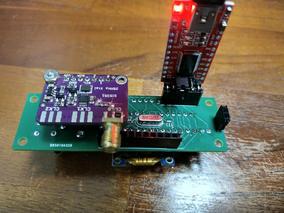
The signal is pulled out from Si5351a module's SMA output. I inserted ATT between SMA and Si5351a output with cut and jumped.
信号はSi5351a モジュールSMAコネクタ出力から取り出しました。また、SMAコネクタ出口には6dBのATTを入れてあります。
I reedited the sketch for the signal generator. I can use this for testing the receivers.
スケッチを少し書き直し、試験ベンチ用VFOとして使うことにしました。
操作ルールは次。
通常キーステイタス0の時はロータリーエンコーダー回すと指定ステップ周波数単位で受信周波数を増減。
ロータリーエンコーダーのプッシュスイッチでステップ周波数単位を変更選択。
機能キー1を押すと設定周波数バンドを次々と切り替え表示していく。160m>80m>40m>....
PCBGOGO
www.pcbgogo.jp

![HiLetgo 0.96" I2C シリアル 128×64 OLED LCDディスプレイSSD1306液晶 STM32/51/MSP430/Arduinoに対応 ホワイト [並行輸入品]](https://m.media-amazon.com/images/I/41nLOEMgTrL._SL500_.jpg "HiLetgo 0.96\" I2C シリアル 128×64 OLED LCDディスプレイSSD1306液晶 STM32/51/MSP430/Arduinoに対応 ホワイト [並行輸入品]")